The Scanner Linearization Panel locates on the right side of the application. It is opened when “Tool – Scanner linearization data editor” in “Background (lateral linearization)” under “Case Data Selector” is selected.
The scanned color value Xscan (x,y) at scanner coordinates (x, y) can be represented as:
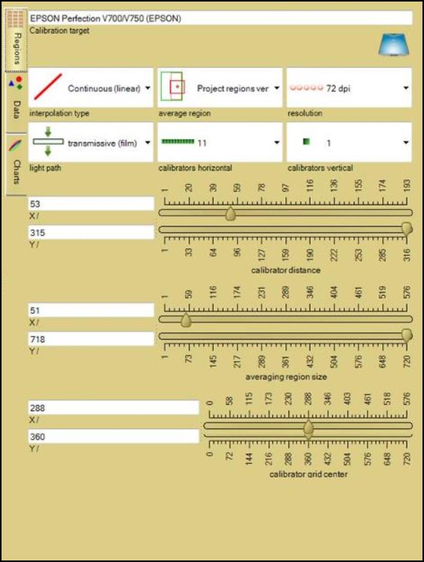
The scanner characterizing function S depends on scanner location and color value X. An ideal scanner would have the function equal to one. The task of the scanner linearization correction is to approximate the scanner characteristic function S. When a background film image is used to calibrate the lateral linearization of the scanner, the scanner is segmented into even grid of color calibrators to mitigate location dependence of scanning results. Each calibrator averages the RGB color channel data over a surrounding region and correlates those data with the scanner center region. The “Scanner Linearization Panel” allows you to view and define calibrator grid regions, calibration function, and calibration chart for the scanner linearization calibration. The panel contains three sub-panels: “Regions Panel,” “Data Panel,” and “Charts Panel.”